


 Home
Home
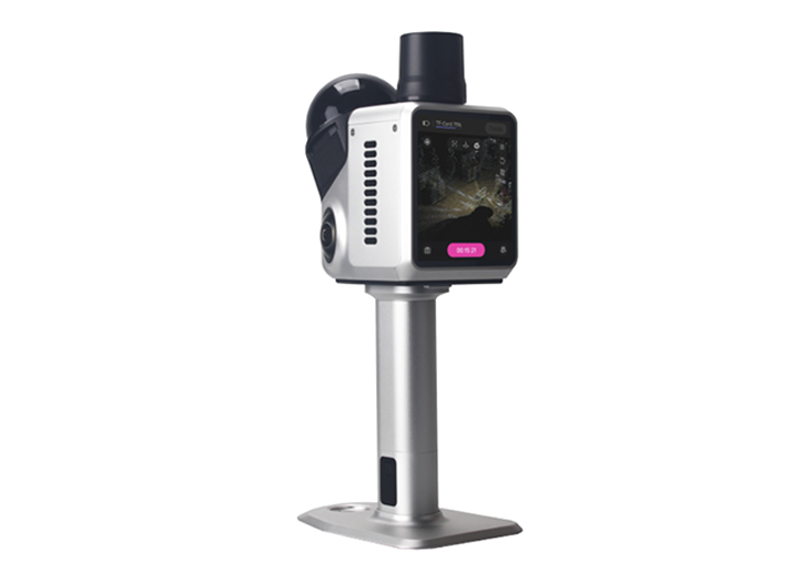
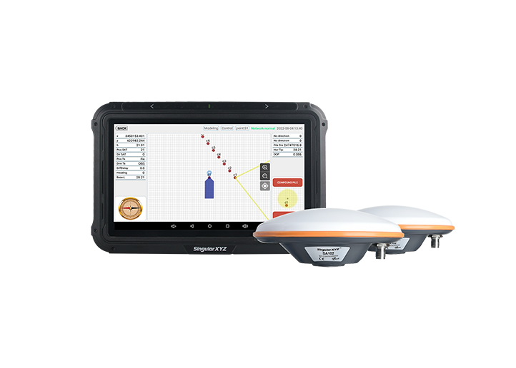
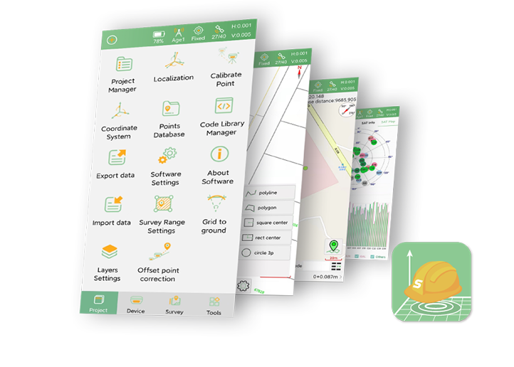
SingularPad Field Surveying Software
learn more


 2026-03-09
 Satoshi


When using CAD drawings for stakeout tasks, users may sometimes find that the imported CAD base map does not align with the coordinates displayed in SingularPad. This usually occurs because the CAD file and the project data use different coordinate systems or reference origins.
SingularPad provides a CAD Calibration function that allows users to align the CAD drawing with the project coordinates by defining several known points. This blog introduces the workflow for aligning CAD drawings in SingularPad.
Tap the Settings icon in the toolbar at the bottom of the software and enter the settings interface. Find Tool Bar, enable the CAD Calibration function, and click OK.

Return to the CAD Stakeout interface and tap the CAD Calibration icon on the left to enter the calibration interface.
To align the CAD drawing, several calibration points need to be defined. These points must have known coordinates corresponding to their positions in the CAD drawing.

Tap the Map Point Coordinates Selection button at the top right corner to enter the drawing interface. Select the Pointer tool on the left and use it to pick points on the CAD drawing. After selecting a point, enter its actual coordinates in the Known Point Coordinates fields below.

For better calibration results, it is recommended to:
Select points located near the edges of the drawing
Choose points that are evenly distributed across the drawing
Use points that form a balanced spatial distribution, such as points near the north, south, east, and west boundaries
This helps improve the overall stability and accuracy of the alignment.
After selecting the calibration points, click Next, then Confirm Calibration to apply the alignment.
Return to the CAD Stakeout interface to verify the result. The CAD drawing should now align with the project coordinates, allowing you to proceed with stakeout operations.

Note
Once calibrated, the CAD drawing will remain in this aligned state unless the calibration is manually canceled in the CAD Calibration tool.
The CAD Calibration function in SingularPad allows users to quickly align CAD drawings with the project coordinate system when different reference frames are used. By defining several known points and assigning their coordinates, CAD files from different sources can be used directly for stakeout work, helping simplify field workflows and improve operational efficiency.