










































 Home
Home
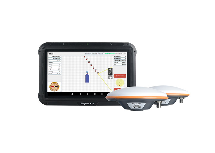
SingularPad Field Surveying Software
learn more





 2026-10-13
 Linden


In engineering design and construction, we often run into this situation: the building itself is not laid out along north–south or east–west lines.
For example, a proposed building sits at an angle relative to the project's global coordinate directions. If you draw and view it in CAD strictly along the original coordinate directions, the building appears tilted, and many dimensions, axes, and point locations that relate to the building's own orientation become hard to interpret intuitively.
In this case, a common practice is to create a UCS (User Coordinate System) in CAD, redefining the coordinate origin and axis directions to match the building's actual orientation. That way, when working on the building's local design, reviewing it, or locating points, you can work directly along the building's own directions instead of always facing a tilted drawing. This is one of the main reasons the UCS is so widely used.
So what exactly do WCS and UCS stand for? Why do the drawing's display orientation and the point coordinates change after switching? And how do you switch between them in SingularPad?
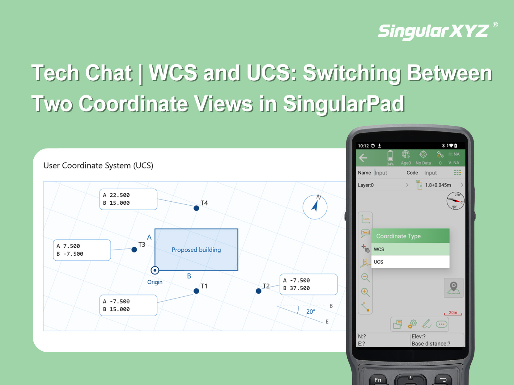
Using a real building scenario as our running example — a proposed 30 m × 15 m building whose long axis is rotated 20° counterclockwise from due east — this article explains the purpose of the UCS, and how to view and switch between WCS and UCS in SingularPad.
WCS (World Coordinate System) is the fixed coordinate frame in a CAD drawing: it has a fixed origin and fixed axis directions. In surveying projects, the WCS orientation usually corresponds to the project's plane coordinate directions — for example, X / Y aligned with east / north. For the SingularPad CAD scenario discussed here, you can think of the WCS as the global reference coordinate frame to which the objects in the drawing belong.
UCS (User Coordinate System), in contrast, is a local coordinate frame defined by the user: you can place the origin wherever is convenient (for example, at a corner of a building) and redefine the axis directions (for example, aligning the axes with the building's long and short axes).
Note: To match the SingularPad example used below, the two horizontal axes of the current UCS are written as A / B; in most CAD software, UCS axes are labeled X / Y / Z.
To make the abstract concepts concrete, we use one fixed scenario throughout: a 30 m × 15 m proposed building whose long axis is rotated 20° counterclockwise from due east (i.e., bearing N 70° E). Four survey points T1–T4 are distributed around the building.
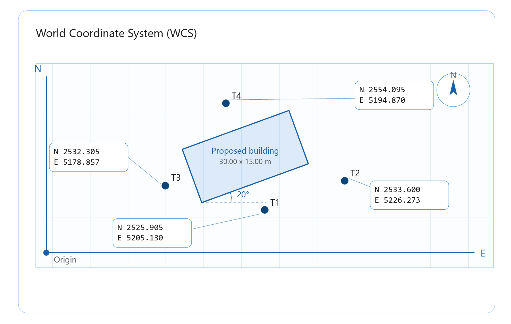
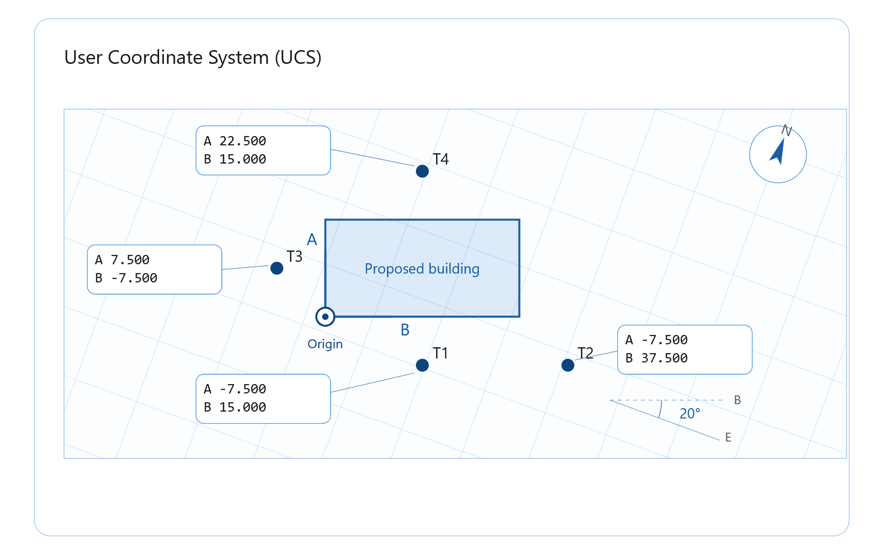
The difference between the two views of the same site can be taken in at a glance:
Item | WCS view | UCS view |
Axis orientation | Keeps the WCS orientation | Aligned with the building, so it appears rotated relative to the WCS |
Building | At 20° to true north, appears "tilted" | "Squared up" into a rectangle parallel to the drawing frame |
Coordinate readout | N / E coordinates in the WCS | A / B local coordinates in the current UCS |
Typical readout (T1) | N 2525.905 / E 5205.130 | A -7.500 / B 15.000 |
In the WCS view: the WCS coordinate orientation is kept; because the building is at a 20° angle to the WCS directions, it appears "tilted" in the drawing; point coordinates are given as N / E values in the WCS, with relatively large numbers (for example, T1 is N 2525.905 / E 5205.130).
In the UCS view (with the UCS origin at the building's lower-left corner — that corner reads A 0 / B 0 in the UCS; the A axis runs along the building's short axis and the B axis along its long axis): the current axes are aligned with the building, so when viewed from the current UCS orientation the building appears as a rectangle parallel to the drawing frame; conversely, the original WCS directions appear rotated by 20° relative to the current UCS.
The two sets of coordinates compare as follows (the same physical point, two expressions):
Survey point | WCS (N / E) | UCS (A / B) |
T1 | 2525.905 / 5205.130 | -7.500 / 15.000 |
T2 | 2533.600 / 5226.273 | -7.500 / 37.500 |
T3 | 2532.305 / 5178.857 | 7.500 / -7.500 |
T4 | 2554.095 / 5194.870 | 22.500 / 15.000 |
As you can see, T1–T4 are expressed in global coordinates under the WCS, while under the UCS they become A / B local coordinates centered on the building, with more intuitive meaning. The UCS does not change these points' actual positions in the WCS; it simply provides another origin and axis orientation for expressing the same physical location.
Using SingularPad as an example, this section explains how to switch between these two display modes in the software. Before you start, prepare a drawing that already has a usable UCS defined; the drawing used above serves as the example.
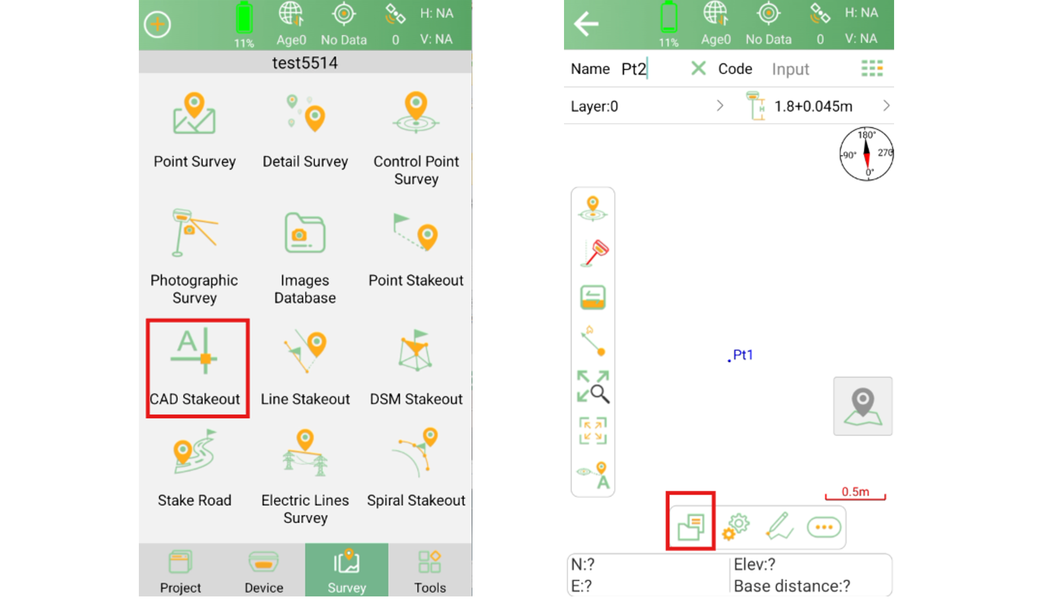
In the software, tap CAD Stakeout, then tap the button below to open the file selection page, which lists previously opened drawings. If you need to open a new drawing, tap "Open …" below.
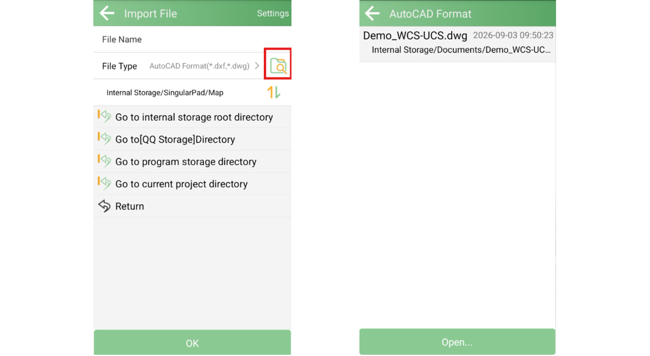
You can import the drawing manually by browsing to its folder path, or tap the search button to have the system automatically search for files with matching extensions; tap the file to open it.
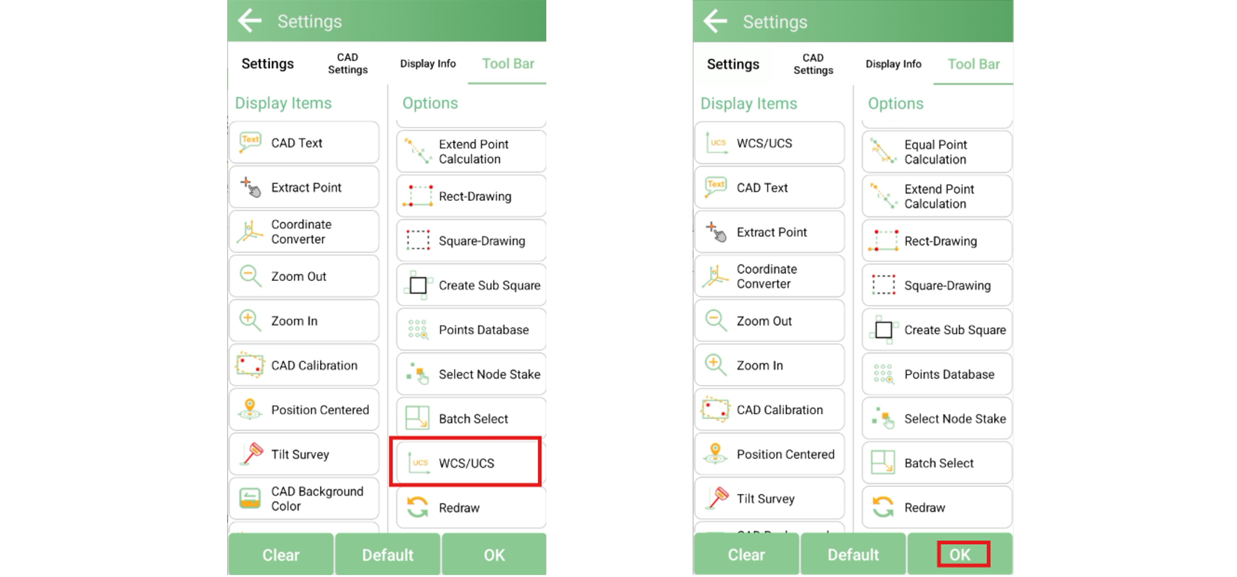
Tap Settings below to open the function menu, select the "WCS/UCS" feature from the options, and add it to the display items; you can drag it up or down to reorder. Tap “OK” to save.
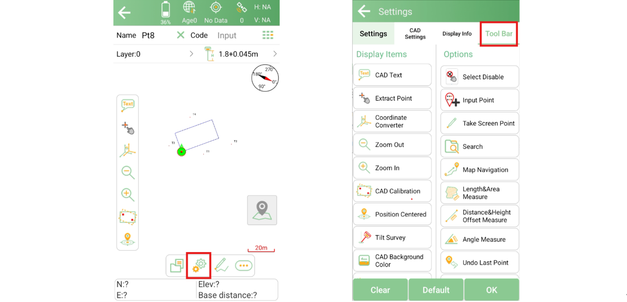
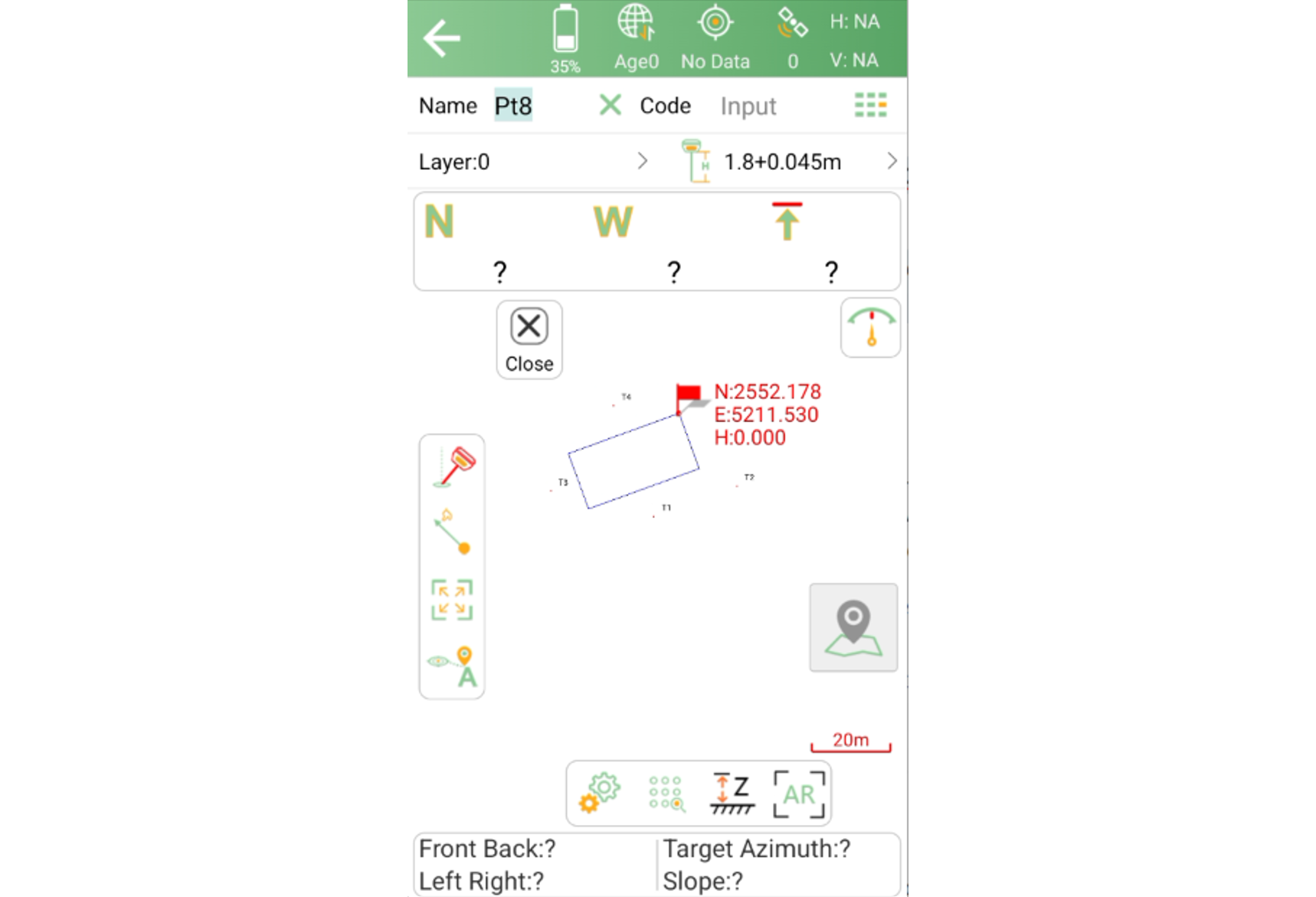
Taking the current drawing as an example: when opened, the drawing is in the WCS state. You can view a point's coordinate display by snapping to it or selecting it.
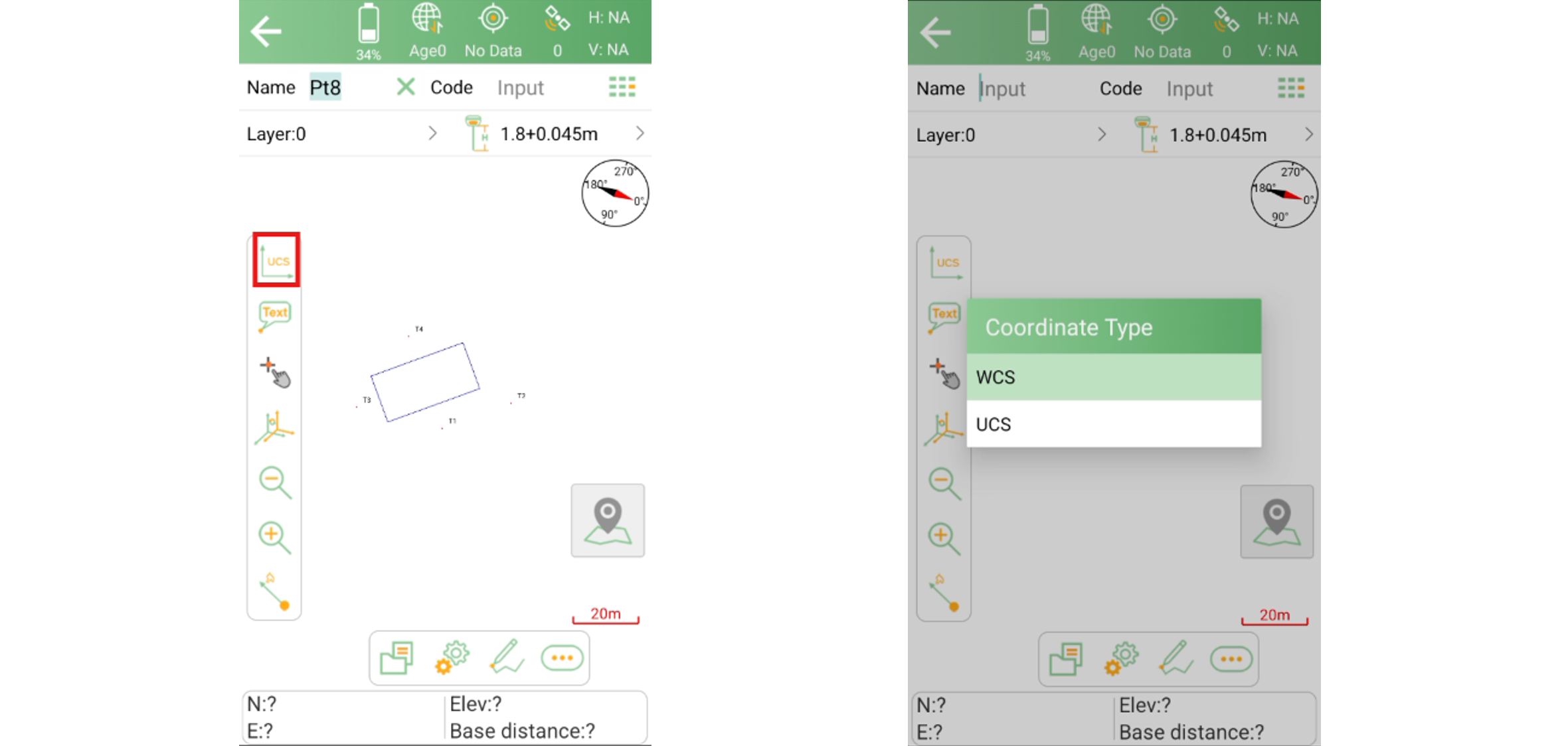
Then tap the UCS icon in the left toolbar — two options appear: "World Coordinate System" and "User Coordinate System" . Select "User Coordinate System", and the system switches to the corresponding UCS expression in the drawing.
After switching, the drawing's display orientation changes — this is because the current viewing and coordinate expression have switched to the UCS orientation, so the building is now aligned with the current axes and visually appears "squared up". The CAD drawing objects themselves have not been rotated.
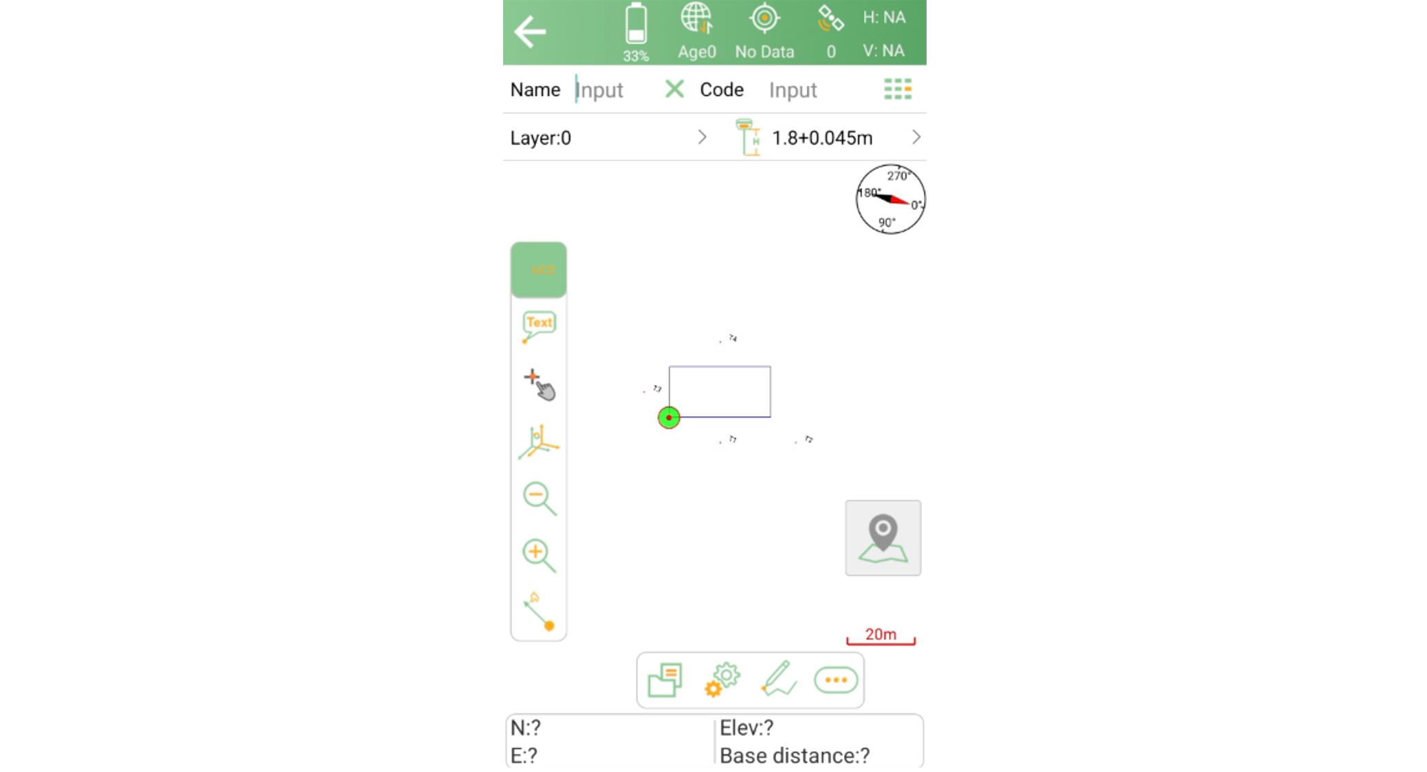
Now look at the coordinate readouts for the same points: under the WCS they are global N / E coordinates; after switching to the UCS they become A / B local coordinates relative to the UCS origin and axis directions, with more intuitive values (compare with the coordinate table in the previous section).
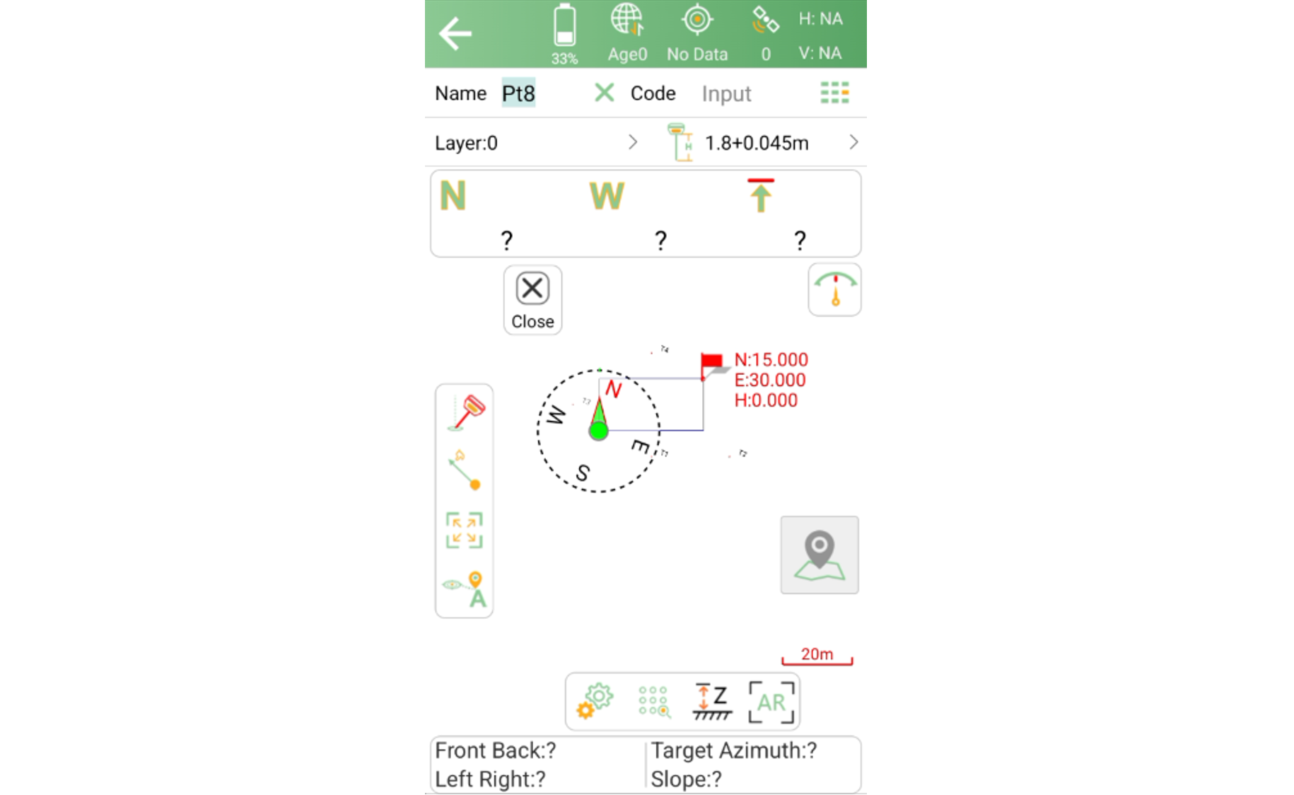
First confirm the drawing contains usable UCS information: In SingularPad, you need a CAD drawing whose UCS information can be recognized; if the drawing has no usable UCS defined, you cannot switch to the corresponding user coordinate system.
Pay attention to the UCS origin location: When reviewing, check whether the origin falls on an easy-to-verify position such as a corner or an axis intersection, so you can tell what datum the A / B readings are referenced to.
WCS and UCS are not two contradictory coordinate systems. Rather, they are two ways of expressing coordinates — with different origins and axis orientations — for the same drawing and the same set of points: the WCS provides a fixed global reference frame, while the UCS establishes a more convenient local coordinate system for a building or work object.
It should be emphasized that, in this SingularPad feature, switching between WCS and UCS mainly changes the drawing's viewing orientation and coordinate display format; switching does not move the points' actual positions in the original WCS, nor does it change the geometric positions of the drawing objects themselves. Understanding the relationship between the two helps you compare global and local coordinates more intuitively when checking drawings and points.
If you run into any problems during configuration or in the field, feel free to contact our technical support team for assistance.